Architecture of wiredflow (for developers)
Sometimes, in order to know a tool, it's worth finding out how it's arranged internally. This section will help to make sense of it. Current page was prepared by the developers for developers.
We have tried to organize the text, diagrams and specifications so that the reader can understand the internals of wiredflow as quickly as possible and be able to start modifying the source code.
How the user sees wiredflow
The user works with wiredflow as a tool for constructing services. That is, the framework in this case is considered from the functional point of view. To construct services, it is necessary to use one of the suggested entities (stages actually):
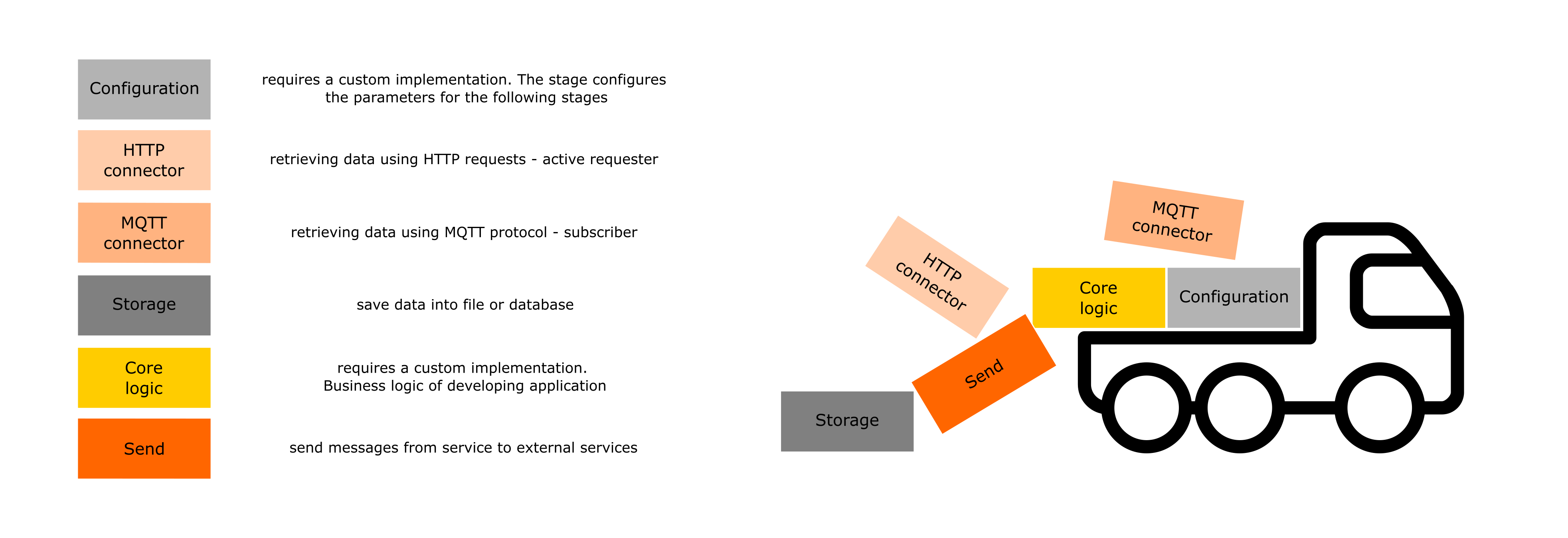
Thus, the user can compile services with a variety of such blocks. All the user needs to know - what blocks there are and how they should be configured correctly. This is the end of the abstractions with which the user interacts.
How the developer sees wiredflow
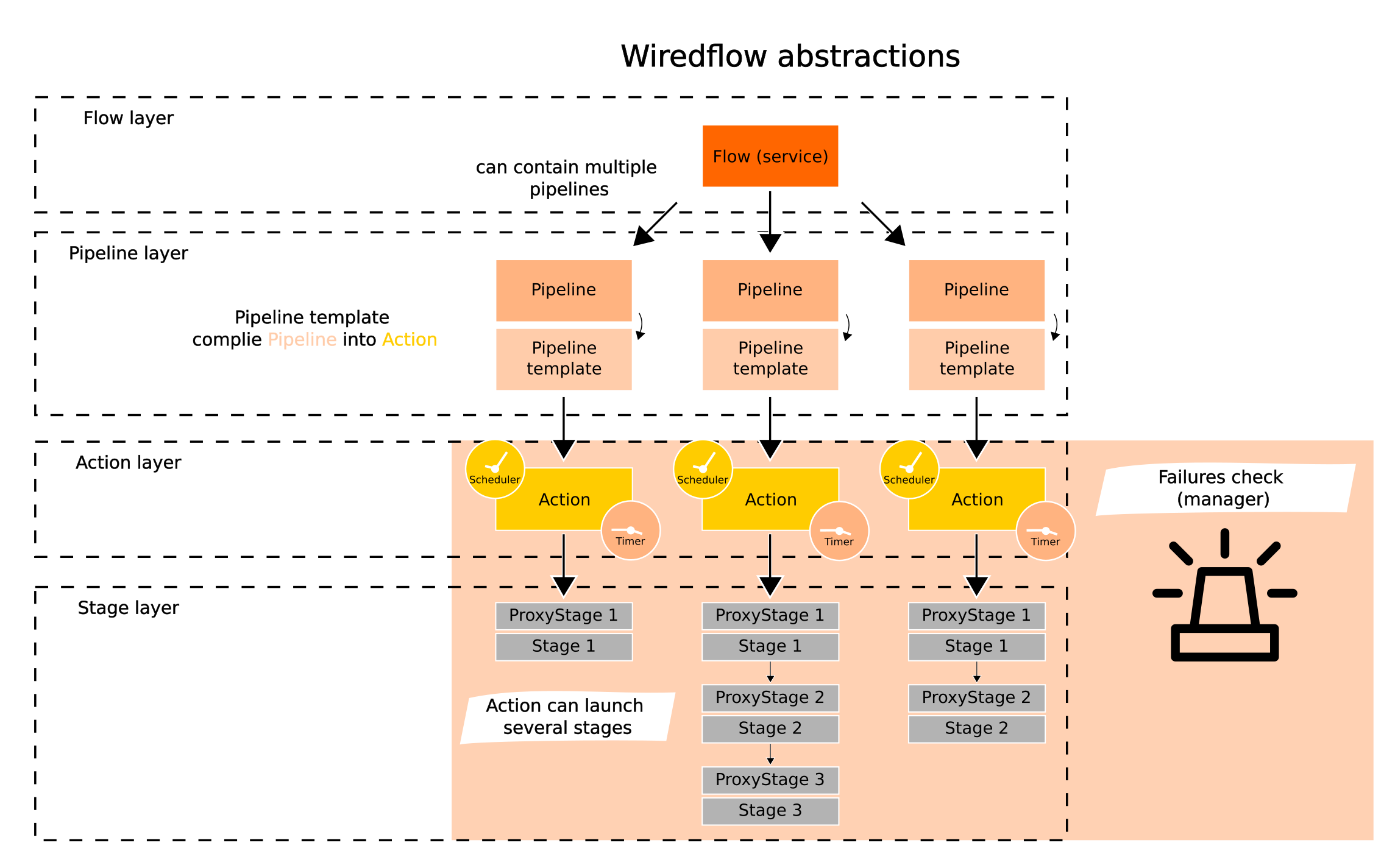
During the framework development we actively use the principles of object-oriented programming and a multi-layer architecture (pretty classic approach). A brief description of the abstraction layers and their functions:
- Builder - builder pattern. Is used to create services (flows) by sequentially adding stages and pipelines to the flow structure;
- Flow - service with pipelines. Runs pipelines in threads or processes;
- Pipeline - storage container for stages. Provides methods to modify its structure;
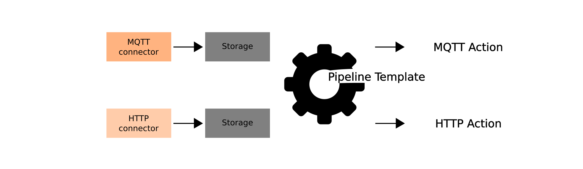
- PipelineTemplate - transforms a pipeline (defines structures) into an executable object - Action. Action type defined based on stages and their order in the pipeline;
- Action - provides a single interface for launching both individual stages and their sequences. Responsible for the correct sequential execution of the stages;
- ProxyStage - wrapper over the stages, - provides transferring and merging arguments in stages and single interface for invoking different stage implementations;
-
Stage - low-level abstraction, which consists of a single operation (just load data, just transform it or load into database);
-
Scheduler & Timer - internal scheduler and timer, measures the execution time of various tasks and stops execution if the time limit is exceeded. Follow defined scheduling during execution;
Failures managers (share information between pipelines):
- FailuresCheck (threads) - singleton for sharing messages about errors during execution of a pipelines, when pipelines are running in threads;
- multiprocessing Manager (processes) - sharing messages about errors during execution of a pipelines, when pipelines are running in processes;
Key abstraction layers
As mentioned above, the architecture of the library is multi-layer. This is done for three main reasons:
- Easier to make changes - enhance functionality (especially when working in a team);
- Isolated abstractions are easier to test and debug;
- More clarity in system behavior.
The layered architecture is especially convenient when new functionality needs to be included in a
library. For example, to implement a new stage for saving data to the database (storage).
Each abstraction "knows" how to communicate with the more low-level one.
This means that Pipeline knows how to compile Action, Action knows how to run ProxyStage,
and ProxyStage knows how to launch Stage.
The interfaces of all descendant classes within the same stage are the same. This
means that in order to use the new implementation of a stage, it will only be necessary to implement
it (It's important that you know exactly how) and "notify" the layer above of the appearance of the new class.
Most of the functionality is concentrated in the core of the framework. And we believe that over time it will expand faster than other modules (such as scheduler or builder): integrations with new databases, connectors and mechanisms for sending notifications will appear. Therefore, we believe that the basic framework will remain unchanged - it will only add new functionality without changing the former. Thus, the abstractions that are likely to be scaled up should be considered in more detail:
- Pipeline and pipeline templates
- Actions
- Proxy Stages
- Stages
Pipeline and pipeline templates
We should start with the pipelines. Flow launches pipelines in individual threads or processes such that the principle: "One thread - one pipeline" is followed.
However, pipelines do not start stages on their own. They are intermediaries, constructs for storing and modifying the sequence of stages but not launching them. This means that Pipeline has methods for modifying its structure. It is also the responsibility of the Pipeline to keep track of the structure and provide relevant information about it. So the pipeline "knows" what stages are included in the ETL process structure.
Pipeline plays an important role as a basic identifier in the service - each pipeline is assigned a name at the moment of its creation. Thus, the logs in the low-level abstractions will operate on the name of the pipelines within which they are executed.
When the pipeline structure is formed, there is a need to run the ETL process. Then the Pipeline needs to be converted to Action. The PipelineTemplate is used for this transformation:
Actions
Action is required to launch the stages in the correct order. This abstraction can also stop the task if the failures manager reports an error or if the execution time is over. Thus, actions control the execution of ETL processes. The interface is unaffected by the number of stages to run and their order.
Proxy Stages
Proxy Stages ensures that arguments are passed to stages correctly. Furthermore, this layer allows different variants of built-in stages as well as custom implementations to be run in a uniform way.
Stages
Stages are the lowest-level abstraction in the framework. It represents a single operation that needs to be performed. For example "retrieve data via HTTP request", "save dictionary into database". The business logic of ETL pipelines is contained in isolated stages classes.